A complete diagnostic and replacement of a faulty Heatmiser UH8-RF wireless wiring centre for a residential underfloor heating system in Hayle, including resolving an underlying switch live wiring fault and purging airlocks to restore boiler functionality.
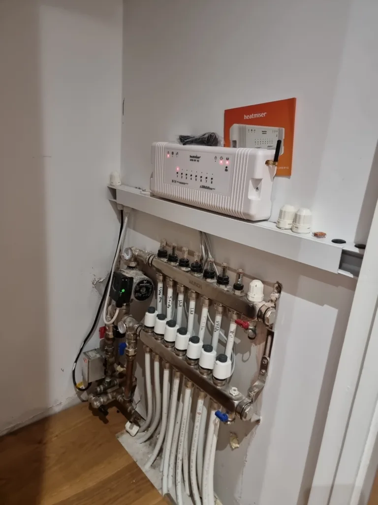
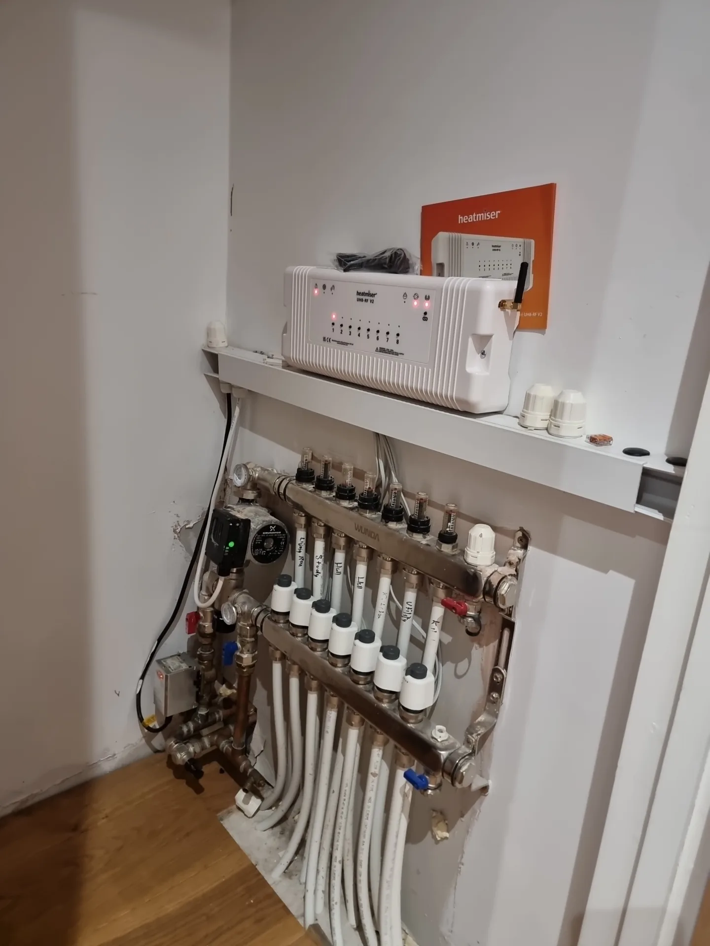
A property in Hayle had an underfloor heating system that refused to warm up, prompting a visit to diagnose the electrical controls. The system relied on a Heatmiser UH8-RF, an eight-zone wireless wiring centre that acts as the communication hub between the room thermostats and the mechanical heating components. When this central unit fails, the individual room thermostats lose their ability to call for heat, leaving the manifold actuators closed and the boiler idle. The initial inspection confirmed that the existing control centre was completely unresponsive and required a like-for-like replacement to restore communication across the heating network.
Have you ever turned up a thermostat and waited hours for a floor to warm up, only to feel cold tiles? This total lack of response usually points to a breakdown at the wiring centre rather than a failure of the mechanical pump or boiler. Before installing the new hardware, the faulty unit needed safe decommissioning. We isolated the 230v electrical supply to the heating circuit and began disconnecting the field wiring. This process involves carefully labelling the incoming supply cables, the pump connections, the boiler enable wires, and the individual zone actuator cables. We also manually un-paired all the existing wireless thermostats from the old receiver memory to prevent any overlapping radio frequency signals when commissioning the replacement unit.
While stripping back the wiring on the faulty unit, a significant installation error in the original setup became obvious. The internal wiring required adjustment because the manifold switch live was entirely disconnected. In an underfloor heating control system, the switch live is the vital outgoing electrical signal that actually fires the boiler. When a room thermostat calls for heat, the wiring centre sends power to open the corresponding thermal actuator on the manifold. Once that valve opens fully, an internal microswitch closes, sending a signal back to the main board. The wiring centre then outputs a 230v feed via the switch live to turn on the system pump and ignite the boiler burner. Without this specific wire connected, the previous setup might have opened the manifold valves, but it never actually commanded the boiler to produce hot water.
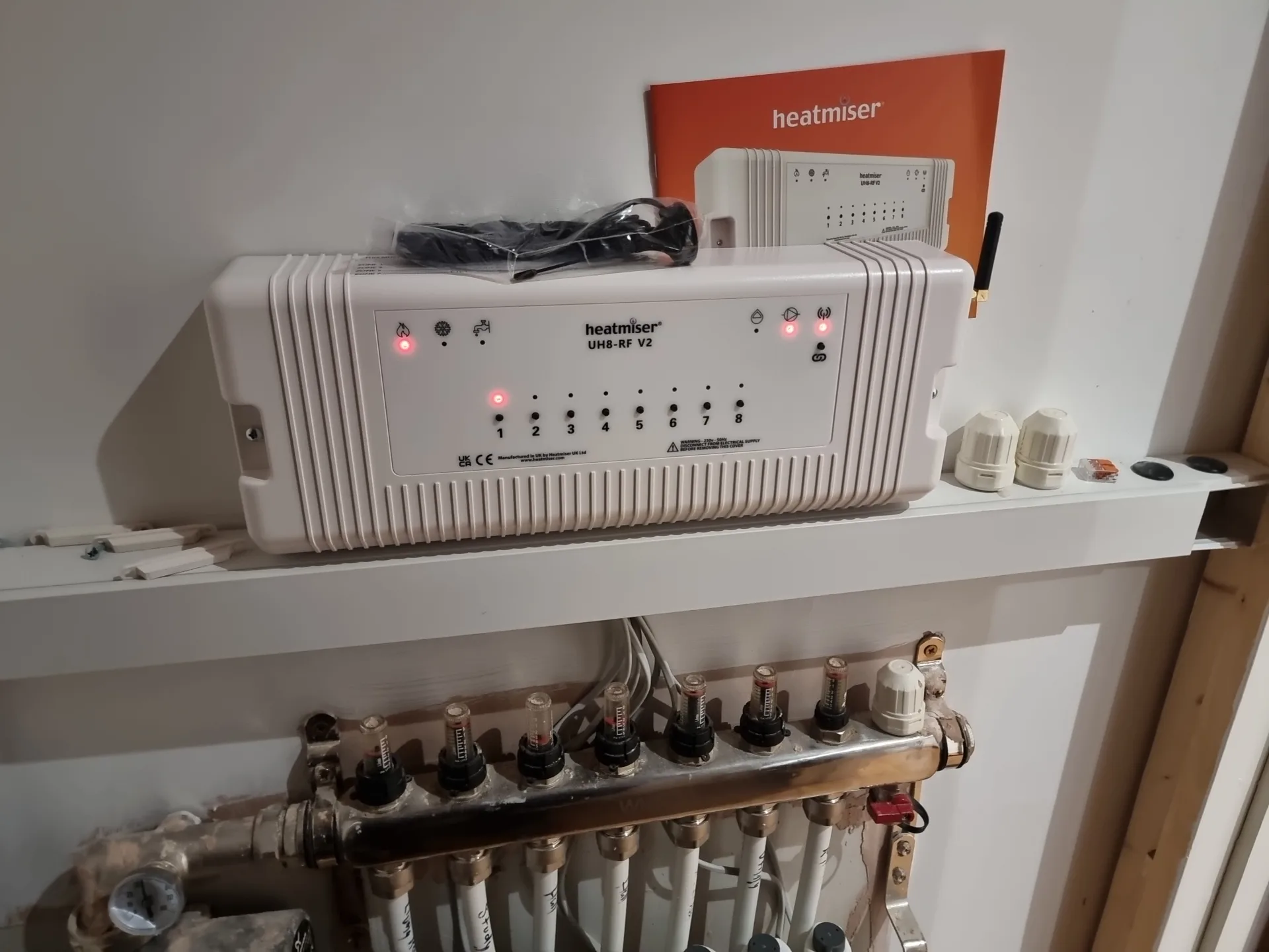
Installing the new Heatmiser UH8-RF involved securing the backplate above the manifold and terminating the corrected wiring configuration. We wired the permanent live, neutral, and earth feeds into the main terminals, followed by the zone actuators. We then routed the newly identified switch live connection directly into the boiler enable relay. This correction guarantees that a heat demand from any room will successfully trigger the heat source. Once the physical electrical connections were tight and secure, we restored the power to begin the digital commissioning sequence.
Syncing the existing thermostats to the new wiring centre requires a methodical approach across the property. We placed the new Heatmiser hub into pairing mode for zone one and walked to the corresponding room to trigger the pairing signal from that specific thermostat. You have to repeat this sequence for every active heating zone, confirming that the radio frequency signal reaches the receiver successfully. As each thermostat paired, the corresponding red LED illuminated on the front of the wiring centre, verifying that the digital communication network was fully operational again.
With the electrical controls communicating properly, the new unit sent power to the manifold actuators, and the corrected switch live finally triggered the boiler to fire. A mechanical issue immediately presented itself during this testing phase. The flow rate through the underfloor pipework was exceptionally poor, and the boiler kept cutting out after only a few minutes of operation. A boiler shutting down prematurely usually indicates an internal safety mechanism triggering due to a lack of water circulation. If the heated water cannot escape the internal heat exchanger quickly enough, the temperature spikes, and the high-limit thermostat cuts the burner to prevent damage.
Listening closely to the manifold and the surrounding pipework, we could hear a large volume of air working its way around under the floor. Hydronic heating systems rely on water as a conductive medium, and any trapped air creates airlocks that block this circulation. An airlock acts like a physical plug inside the pipe, and the system pump simply cannot generate enough pressure to push the water past it. This lack of movement causes the exact rapid-overheating symptoms the boiler was displaying.
To resolve this circulation blockage, we used the newly installed controls to force all the heating zones open simultaneously. By creating a continuous heat demand across the entire manifold, the system pump engages at maximum capacity without pushing against closed valves. This action forces the trapped air through the continuous loops of underfloor pipework and drives it back towards the manifold. We explained the mechanics of this self-purging process to the customer, noting that the pump needs continuous running time to physically shift the air bubbles towards the automatic air vents located on the manifold headers.
The heating system ran continuously with all the zone valves manually overridden to the open position. As the pump forced the water through the unblocked circuits, the flow meters on the manifold began to register a steady, downward pull, indicating proper water movement. The loud gurgling noises of the trapped air slowly dissipated as the vents expelled the pressure. The boiler maintained a constant burn without hitting its safety shut-off limit, confirming that the mechanical purging process successfully resolved the flow restrictions alongside the newly corrected electrical controls.