Relocating a heating air sensor to a more practical position above kitchen cupboards in Mylor Bridge, extending control cabling and making good where necessary to maintain a clean, professional finish.
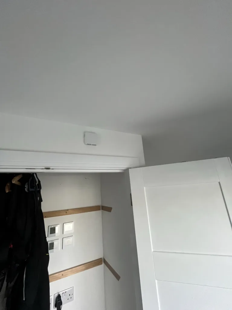
Getting your heating controls in the right spot makes a genuine difference to how your system performs. When a sensor sits in the wrong location, it can read temperatures that don’t reflect how the rest of your home actually feels, leading to rooms running too hot or too cold throughout the day. This work in Mylor Bridge involved moving a heating air sensor from its original wall position to a new spot on the front of a cupboard, positioned just above the doors where it could monitor room temperature more effectively.
The relocation required careful planning around the existing control cabling. Rather than installing entirely new wiring, the existing cables were extended to reach the new mounting position. This approach keeps disruption to a minimum whilst maintaining the integrity of the control circuit between the sensor and the heating system. Extending control cabling isn’t simply a matter of joining wires together – the connections need to be secure and properly insulated to prevent any interference with the low-voltage signals that travel between the sensor and the heating controls.
Working in occupied homes means thinking about how the installation will look once everything’s back in place. The new position above the cupboard doors provides better air circulation around the sensor, allowing it to take more accurate readings without being influenced by direct heat sources or cold spots that might have affected its previous location. Mounting the unit on the cupboard front also keeps it accessible for any future adjustments or battery changes whilst keeping it out of the way during daily kitchen use.
Cable routing presented the main technical challenge during this relocation. Getting cables from the original position to the new mounting point meant working with the property’s existing structure. In some areas, running cables through the wall cavity provided the neatest solution. Where this wasn’t possible, surface-mounted cable routes were carefully planned to follow existing architectural features, keeping visual impact minimal whilst protecting the cables from damage.
The process involved making openings in the plasterboard to access the wall cavity and create routes for the extended cabling. These weren’t large holes, but they needed to be precisely located to allow cables to pass through without snagging on timber studs or other hidden obstacles within the wall. Once the cabling was in place and the sensor mounted in its new position, attention turned to making good the areas that had been disturbed during the installation.
First filling these openings creates the foundation for a smooth finish. The initial fill brings the patched area roughly level with the surrounding plasterboard, though it’s left slightly proud to allow for any shrinkage as the filler cures. This first fill stage prepares the surface for subsequent fine filling, sanding and decoration, which would be completed by others. Making good properly matters because rushed patchwork shows through painted surfaces, no matter how many coats go over the top.
Temperature sensors work by monitoring the air around them and sending signals to the heating system’s control unit. When that sensor sits somewhere that doesn’t represent the general temperature of the room, the whole system responds based on skewed information. Perhaps it was tucked in a corner where air didn’t circulate well, or maybe it sat too close to an external wall that stayed cooler than the rest of the space. Whatever the reason for its original placement, the new position addresses these issues by placing the sensor in a location where air moves freely and temperatures stay consistent with the room as a whole.
The cupboard mounting also provides some practical advantages beyond temperature monitoring. Being positioned above the doors means the sensor stays out of reach of accidental knocks and bumps that can happen in busy kitchens. It’s high enough to avoid steam from kettles or cooking, which could potentially interfere with readings if the sensor sat lower down. Yet it remains accessible should anyone need to check the display or make manual adjustments to temperature settings.
Control wiring for heating systems typically uses multi-core cable with each conductor serving a specific purpose in the communication between sensor and controller. Extending this wiring means matching cable types and maintaining proper connections throughout the extended run. Any weak points in these connections could lead to intermittent faults or complete loss of communication between components, so the joins need to be made with care and tested thoroughly before closing everything back up.
Mylor Bridge properties often feature a mix of construction styles and ages, which can present interesting challenges when working with existing electrical and heating systems. Older properties might have solid walls rather than cavity construction, requiring different approaches to cable routing. More modern builds typically offer more options for concealed cable runs, though you still need to work around insulation, vapour barriers and other elements of contemporary building methods.
This particular installation benefited from cavity wall construction, which allowed most of the extended cabling to run concealed within the wall structure. Where cables did need to surface, they were routed carefully to follow natural lines in the room’s layout. The sensor itself sits flush against the cupboard face, with the mounting plate secured firmly to handle the unit’s weight whilst providing a stable base for accurate temperature sensing.
Heating control systems have become increasingly sophisticated over recent years, with many sensors now incorporating wireless communication or smart features that allow remote adjustment via smartphone apps. Even more traditional wired sensors like the one relocated here benefit from precise positioning because they form a critical part of the feedback loop that keeps heating systems running efficiently. When sensors provide accurate information, boilers fire only when needed and rooms stay at comfortable temperatures without wasteful overheating.
The cabling extension work needed to account for the increased distance between the sensor’s old and new positions. Cable runs were measured carefully to avoid excess length that could create untidy loops or bulges behind finished surfaces, whilst allowing enough slack for the final connection at each end. Control cables generally don’t carry much current, but they do transmit low-voltage signals that need to arrive at their destination without degradation or interference from other electrical systems in the property.
Positioning sensors away from heat sources, draughts and direct sunlight helps them monitor room temperatures rather than localised hot or cold spots. The new location above the cupboard doors achieves this by sitting in an area where air circulates naturally through the kitchen space. Being mounted on the cupboard face rather than the wall behind also means the sensor isn’t influenced by temperatures within the wall structure itself, which can vary considerably from room temperature depending on insulation levels and external conditions.
Making good the disturbed plasterboard involved cleaning back the edges of any openings to create sound surfaces for the filler to bond against. Loose plaster or crumbling edges would compromise the patch, potentially leading to cracks appearing over time as the building moves with seasonal temperature changes. The first fill brings the repair level with surrounding surfaces, ready for fine filling that will create a smooth base for decoration.
Testing the relocated sensor confirmed proper operation before finishing the installation. The sensor needs to communicate effectively with the heating system’s main controller, sending temperature readings and responding appropriately when the system calls for heat or switches to a lower setting. These tests verify that the extended cabling hasn’t introduced any faults and that all connections remain secure under normal operating conditions.